Mechanical Design Portfolio
Skip to:
.jpg)
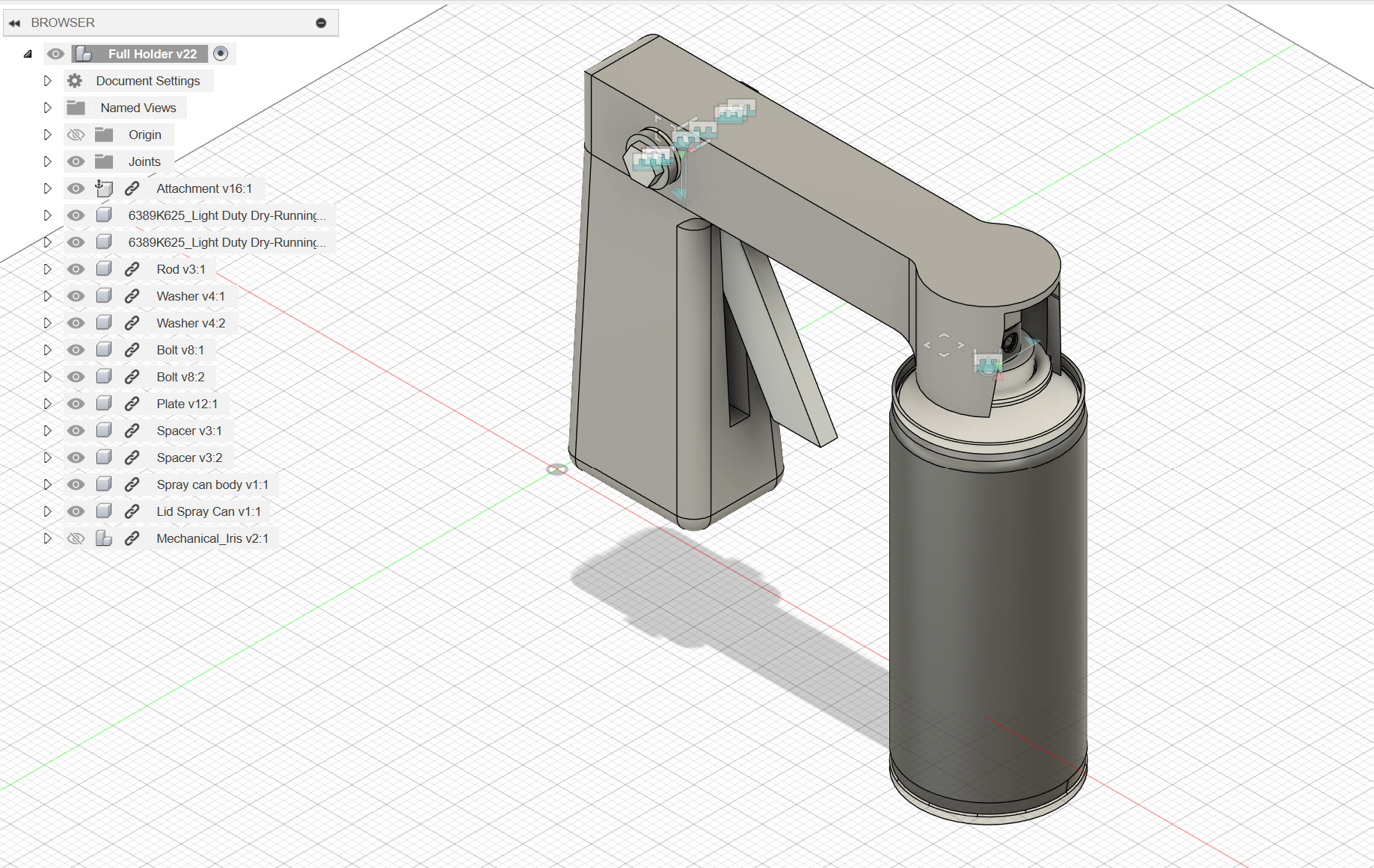
Spray Can Handle & Trigger
Course: Engineering 29 – Manufacturing and Design Communication
Designed and fabricated an ergonomic spray can attachment to reduce finger fatigue and improve spray control for users—including those with arthritis. The final prototype features 11 components, each selected and manufactured for functionality, cost-efficiency, and user comfort:
- Handle: Tough 1500 resin, SLA 3D printed for strength and snap-fit flexibility
- Trigger: Aluminum, bandsawn and drilled for durability and reliable pivoting
- Tapped Rod: Aluminum, lathed and threaded to hold the trigger in place
- Bushings & Spacers: PLA and aluminum respectively, ensuring smooth rotation and spacing
- Washers & Nuts: Aluminum, lathed and milled to meet specific tolerance requirements
The L-shaped lever mechanism inside the handle translates a squeezing motion into vertical force on the spray can nozzle. Key tolerances were maintained using manual lathes and precision 3D printers. The design prioritizes ease of use, reusability, and manufacturability.
Future improvements include switching to injection molding for cost-effective mass production and redesigning the handle's weight distribution to be more comfortable. This project incorporated CAD modeling, material testing, tolerance analysis, and prototyping, and was guided by real-world constraints in design for manufacturing.
Composite Layup and Tensile Testing
Course: Mechanical Engineering 127 – Introduction to Composite Materials
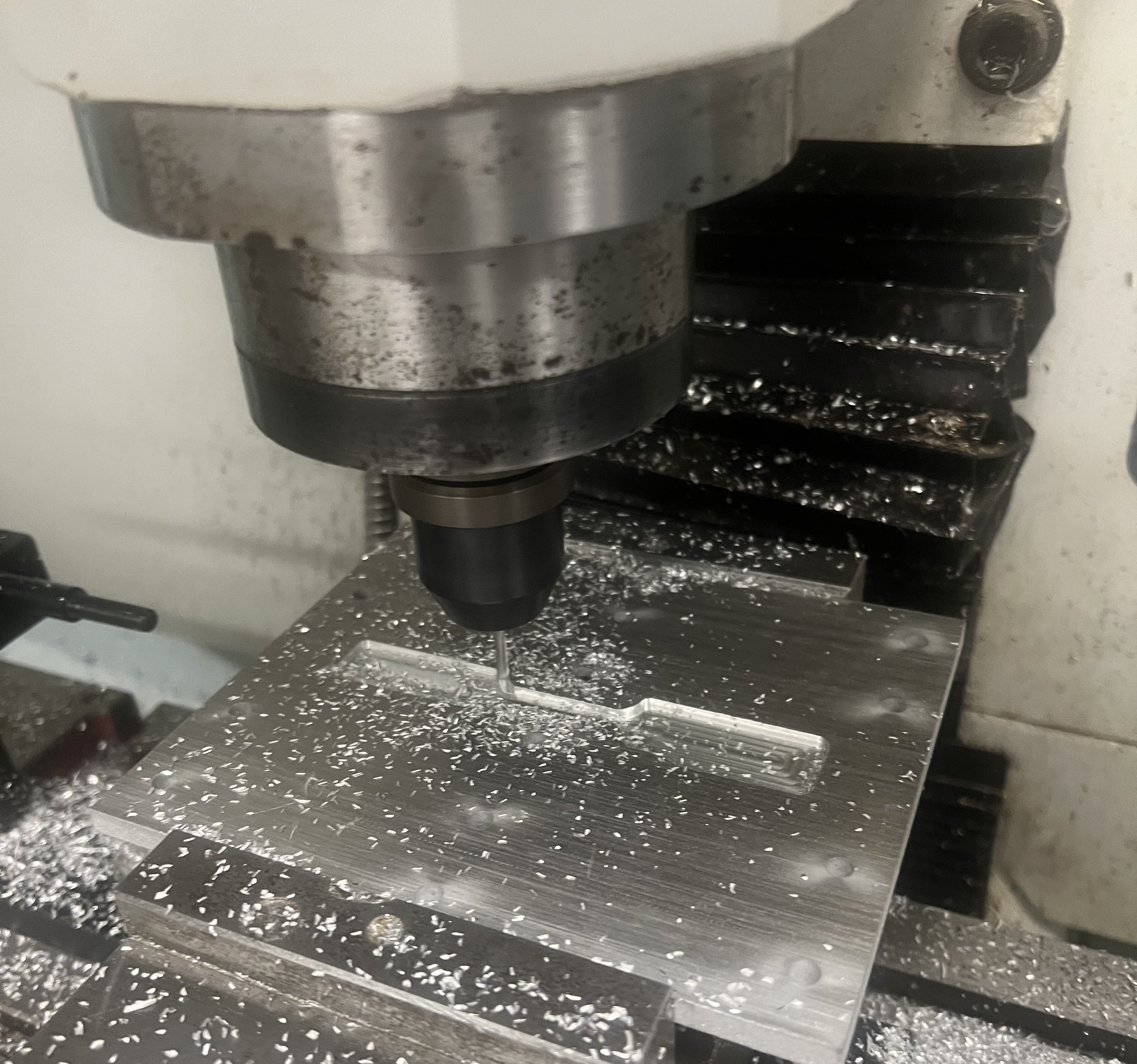
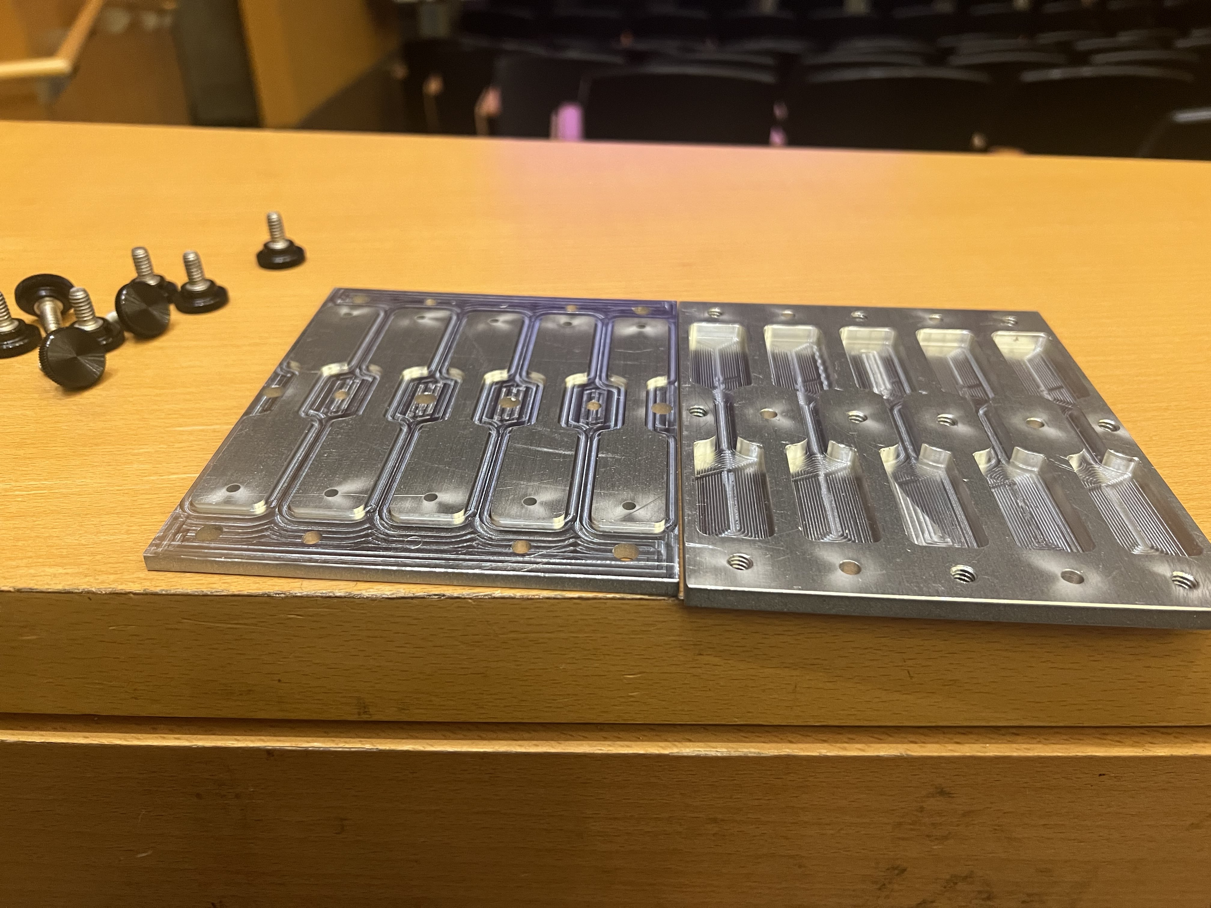
Conducted a research-based project on the tensile performance of epoxy composites reinforced with chopped carbon fiber and colloidal silica fillers. Using ASTM D638 Type IV dog-bone geometry, samples were cast with a CNC-machined aluminum mold and tested to evaluate mechanical strength, stiffness, and fracture behavior.
- Prepared, mixed, and degassed filled and unfilled epoxy resin systems under vacuum
- Utilized a precision aluminum mold and followed controlled curing and post-curing protocols
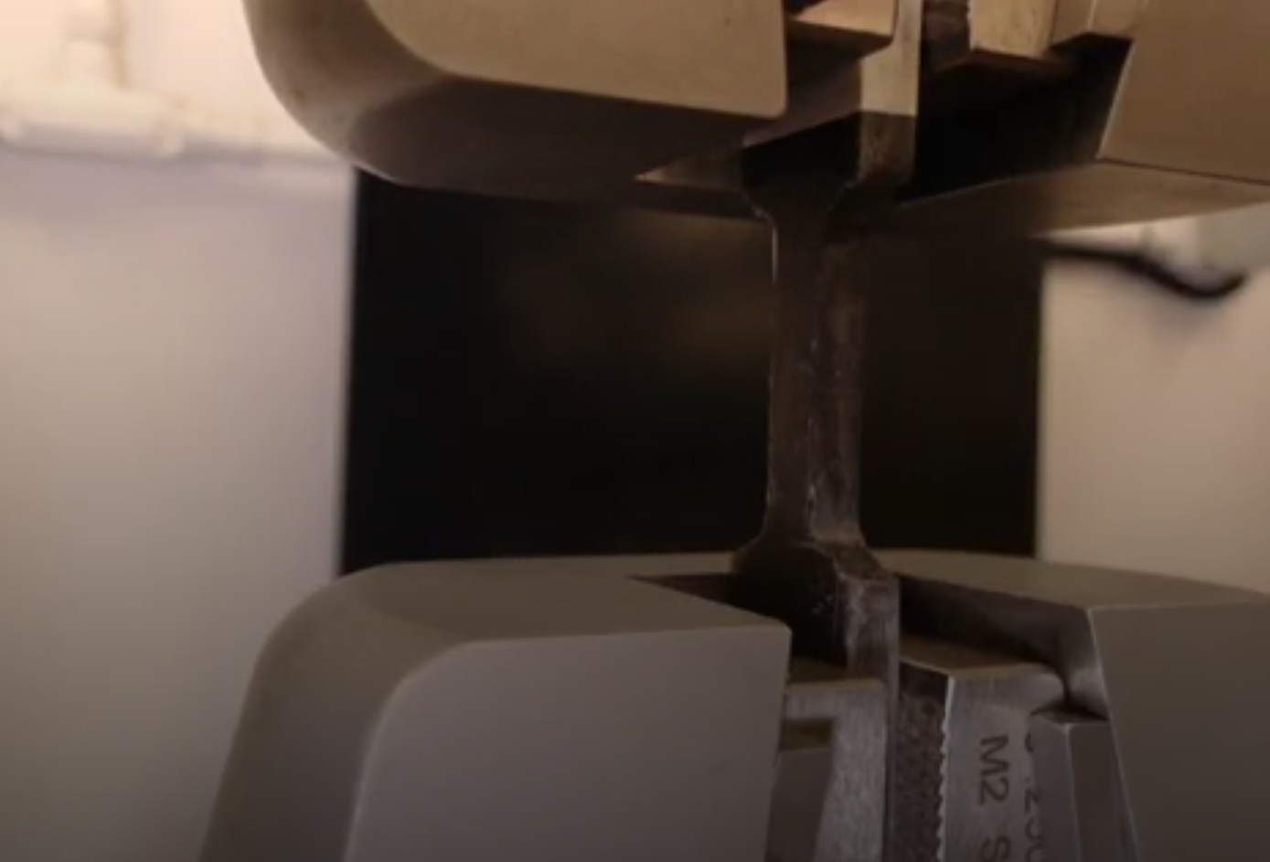
- Performed uniaxial tensile testing on an Instron UTM per ASTM E8 and D3039 standards
- Processed experimental data and generated stress-strain curves using MATLAB
- Compared experimental modulus values to theoretical models (Halpin-Tsai, Rule-of-Mixtures)
The study found that chopped carbon fiber improved ultimate tensile strength and toughness relative to neat epoxy, while colloidal silica was less effective and presented fabrication challenges. Results highlighted the real-world impact of filler dispersion and processing constraints on composite performance.
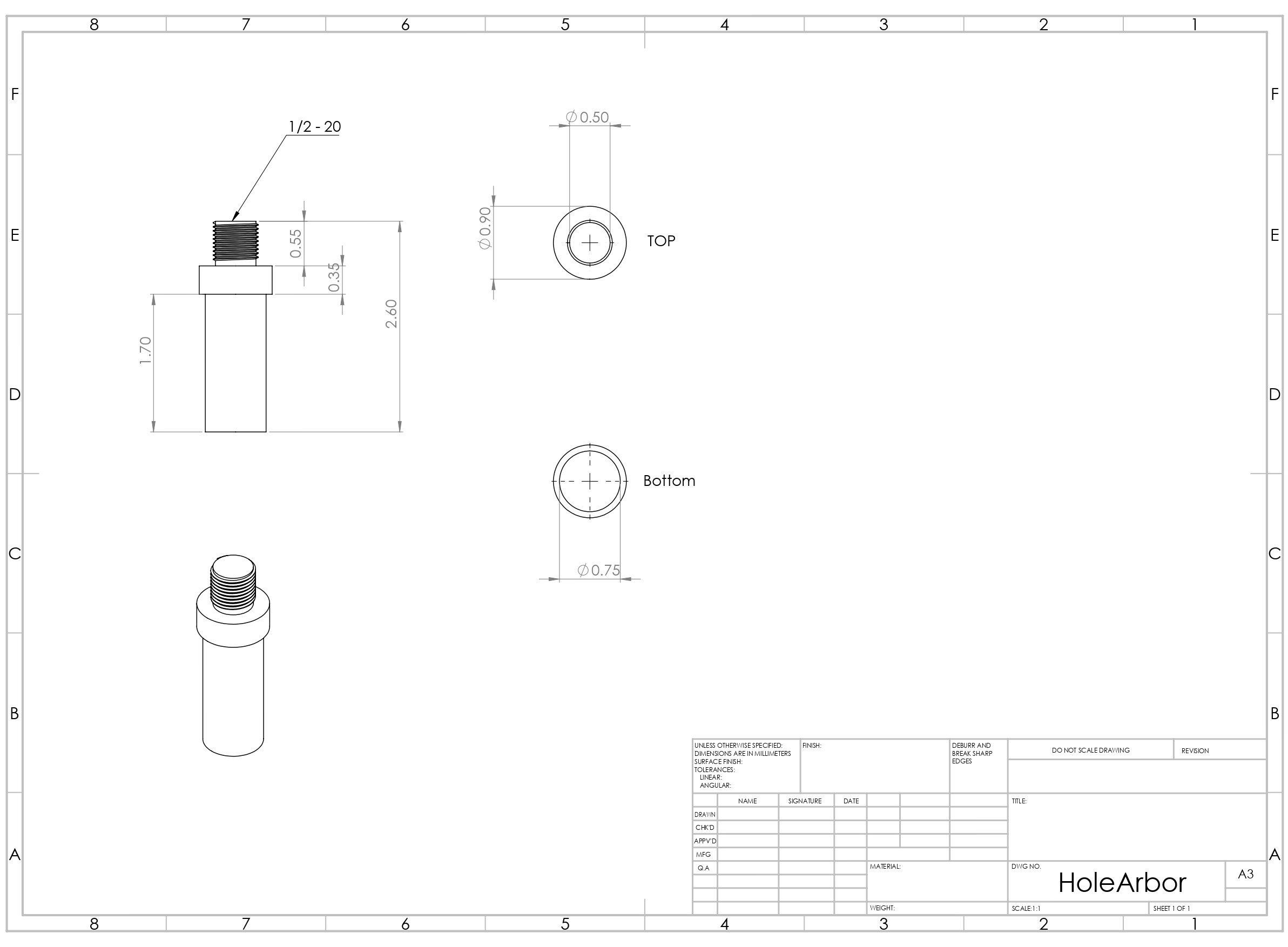
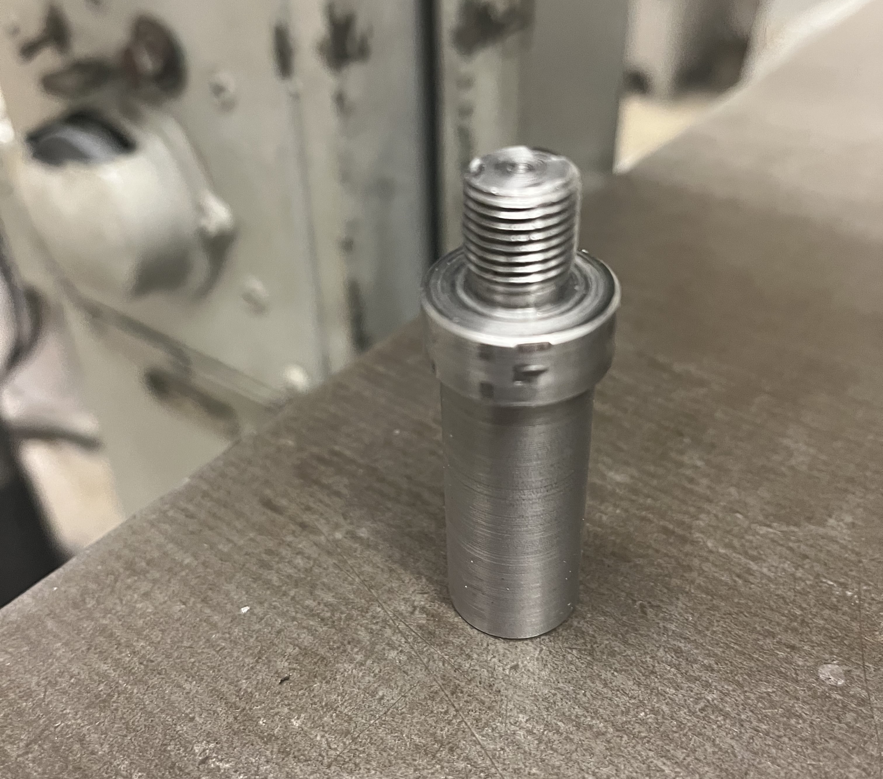
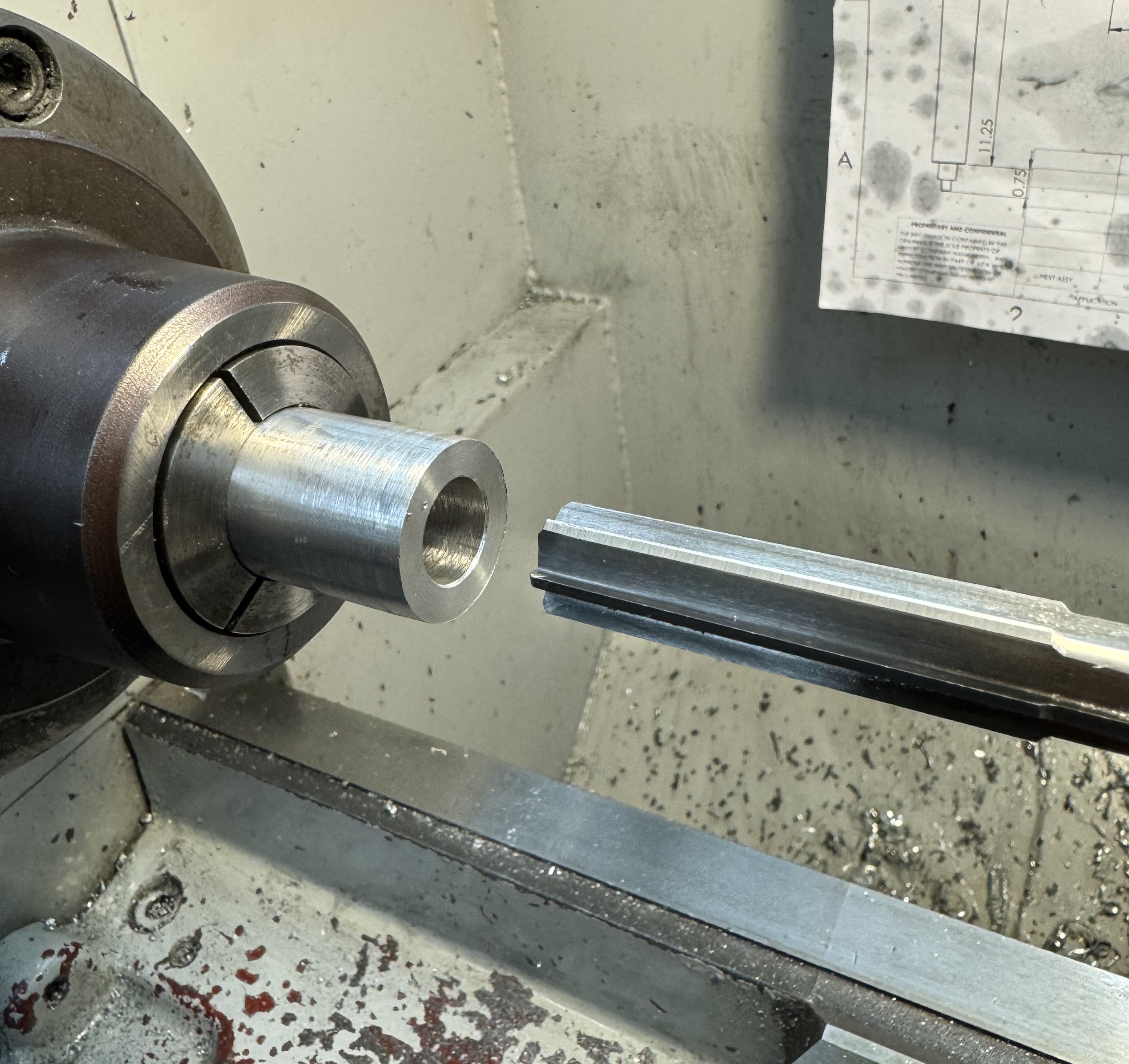
Hole Saw Arbor
Role: Work Study Assistant Machinist at UC Berkeley Machine Shop
Designed and machined a custom hole saw arbor to adapt a different threaded tip size while maintaining compatibility with existing tooling. The goal was to produce a version that could accept a hole saw with matching thread dimensions on one end, and fit into the mill’s collet on the other.
After finalizing the dimensions in Fusion 360 based on a reference arbor, I printed a technical drawing and sourced appropriate steel stock. The raw stock was cut to length, then turned and faced using a carbide cutting tool on a manual lathe to achieve the required fit and surface finish.
- Modeled arbor geometry in Fusion 360
- Printed a dimensioned technical drawing for shop use
- Cut steel stock to length and machined features entirely on the lathe
- Threaded tip modified to accept alternate hole saw while preserving thread spec
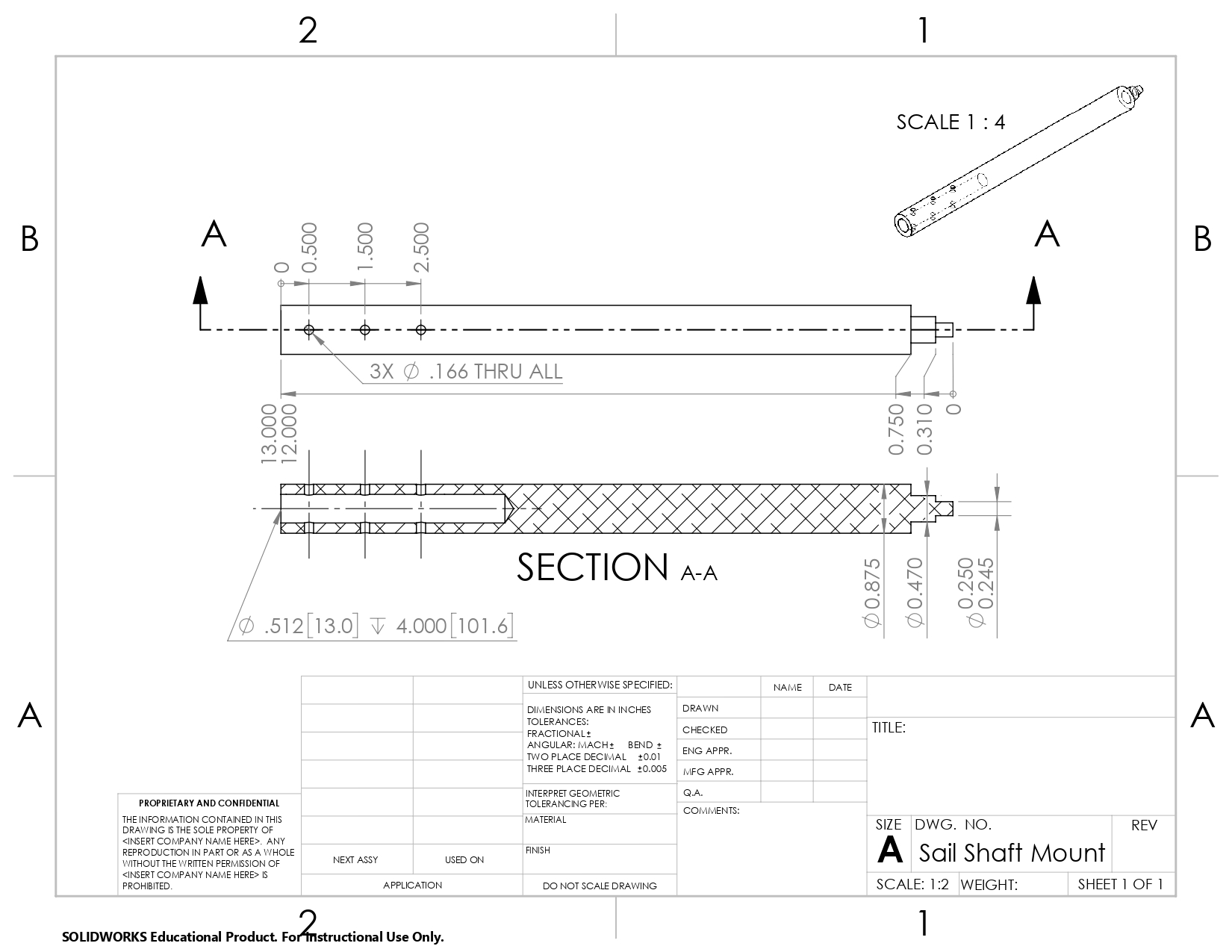
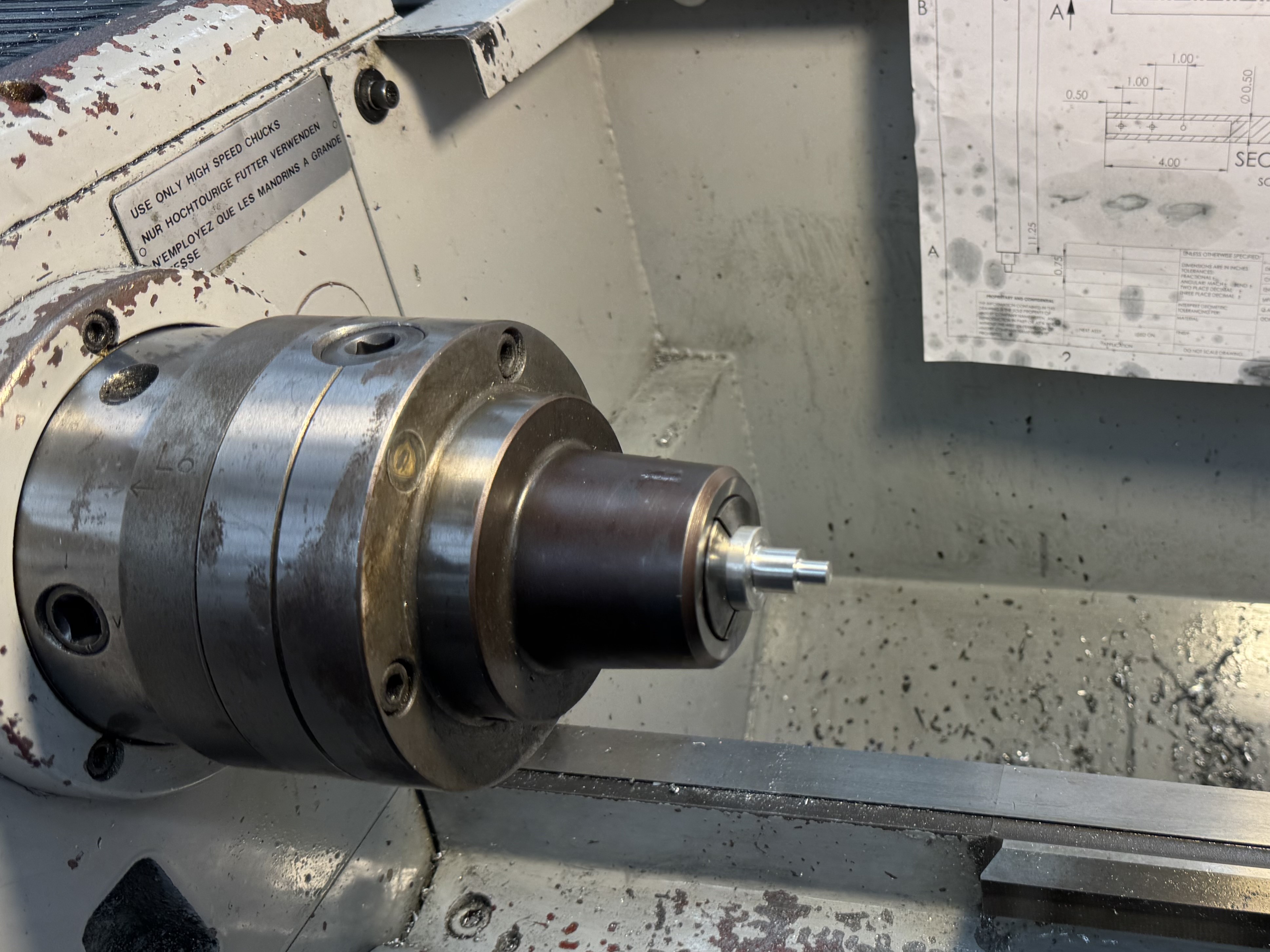
Ocean Drone Sail Rod
Lab: Theoretical & Applied Fluid Dynamics Lab (TAFLab)
Collaborated with graduate researchers at the TAFLab to design, model, and prototype a precision sail rod mount for the Ocean Swarm Drone, a wind-powered autonomous marine vehicle used for distributed ocean monitoring.
I was responsible for translating the structural constraints into a manufacturable geometry, selecting corrosion-resistant materials for marine environments. The design underwent several revisions to account for tolerancing limits in both fabrication and final assembly.
- Modeled and dimensioned the sail rod in Fusion 360, targeting minimal weight and maximum bending stiffness
- Specified 6061-T6 aluminum for corrosion resistance and strength-to-weight ratio in saltwater environments
- Machined prototype using manual lathe and mill, including boring operations and precision facing/turning
- Collaborated closely with graduate students to refine part fit and ensure test readiness.
The successful prototype contributed to the drone’s ability to maintain heading and stability in wind-driven trials. Future work may incorporate composite layups or anodizing treatments to further reduce weight and extend service life. This project exemplified applied mechanical design under real-world fluid-structure interaction constraints, with an emphasis on manufacturability and environmental durability.